
Guía del ingeniero sobre equipos de tamizado: Un análisis técnico de los principios básicos
Introducción
Los ingenieros de procesos y los responsables de calidad necesitan algo más que folletos de productos. Necesitan un conocimiento profundo y funcional de los equipos que impulsan sus operaciones. Esta guía va más allá de las descripciones superficiales. Desglosa los principios básicos de ingeniería que rigen todos los equipos de tamizado.
Nuestro objetivo es sencillo. Queremos proporcionarle una base sólida en la separación de partículas. Exploraremos la física que hace que el tamizado funcione. Examinaremos la mecánica diseños que utilizan estos principios. Y trataremos la ciencia de los materiales que define los puntos de separación.
Este viaje le proporcionará las herramientas necesarias para diagnosticar problemas, optimizar procesos y tomar decisiones de compra inteligentes. Lo cubriremos todo, desde la dinámica básica de partículas hasta los sistemas ultrasónicos avanzados. Nos centraremos en conceptos clave como la eficacia de la separación y la optimización del rendimiento.
Física fundamental de la separación
El cribado tiene que ver fundamentalmente con la probabilidad, no con la perfección. Es un juego de azar, no un filtro absoluto. La eficacia de cualquier operación de tamizado depende de una cosa: maximizar la probabilidad de que una partícula se encuentre con una abertura de la criba y la atraviese.
Para que una partícula atraviese con éxito una malla de tamiz, deben cumplirse dos condiciones. En primer lugar, la partícula debe llegar a una abertura abierta. En segundo lugar, sus dimensiones deben ser menores que las de la propia abertura, dada su posición.
Todo el diseño de los equipos de tamizado se centra en crear un movimiento que haga que estas dos condiciones se den repetida y rápidamente. Esto se consigue aplicando fuerzas específicas al lecho de material.
Las principales fuerzas utilizadas en el tamizado industrial son la gravedad, la vibración, la fuerza centrífuga y la presión del aire. La gravedad proporciona la fuerza descendente básica. Pero a menudo no es suficiente por sí sola, especialmente con polvos finos o pegajosos.
La vibración es el multiplicador de fuerza más común. Fluidifica el lecho de material, rompe los enlaces entre partículas y presenta constantemente nuevas partículas a la superficie de la criba.
La fuerza centrífuga se utiliza en diseños específicos para lanzar partículas contra la pared de la criba a gran velocidad. Esto funciona bien para romper aglomeraciones y para el cribado de alto rendimiento. La presión del aire, utilizada tanto en sistemas positivos como de vacío, ayuda a dispersar los polvos finos y a arrastrarlos a través de la malla.
La eficacia de estas fuerzas depende en gran medida de las características de las partículas. El tamaño de las partículas es la variable principal. Pero la forma, la densidad y las propiedades de la superficie también desempeñan un papel fundamental.
Las partículas de forma irregular tienen menos posibilidades de presentarse en una abertura con una orientación transitable que las partículas redondas. Las propiedades de la superficie, como la humedad, la pegajosidad y la carga estática, pueden hacer que las partículas se aglomeren o cieguen el tamiz. Esto perjudica gravemente la eficacia de la separación. Comprender estas propiedades de los materiales es el primer paso para seleccionar el mecanismo de cribado adecuado.
Mecanismos de los equipos de cribado
El variado mundo de los equipos de tamizado puede organizarse según el principio mecánico principal utilizado para lograr la separación. Cada mecanismo aplica fuerzas de una forma distinta. Esto lo hace adecuado para materiales y objetivos de proceso específicos. Comprender estas diferencias fundamentales es esencial para seleccionar el equipo adecuado.
Tamices vibratorios
Los tamices vibratorios son el tipo más común en el procesamiento industrial. Utilizan la vibración inducida para fluidificar el material y ayudar a la separación. Esta categoría se divide en dos diseños principales: giratorio y lineal.
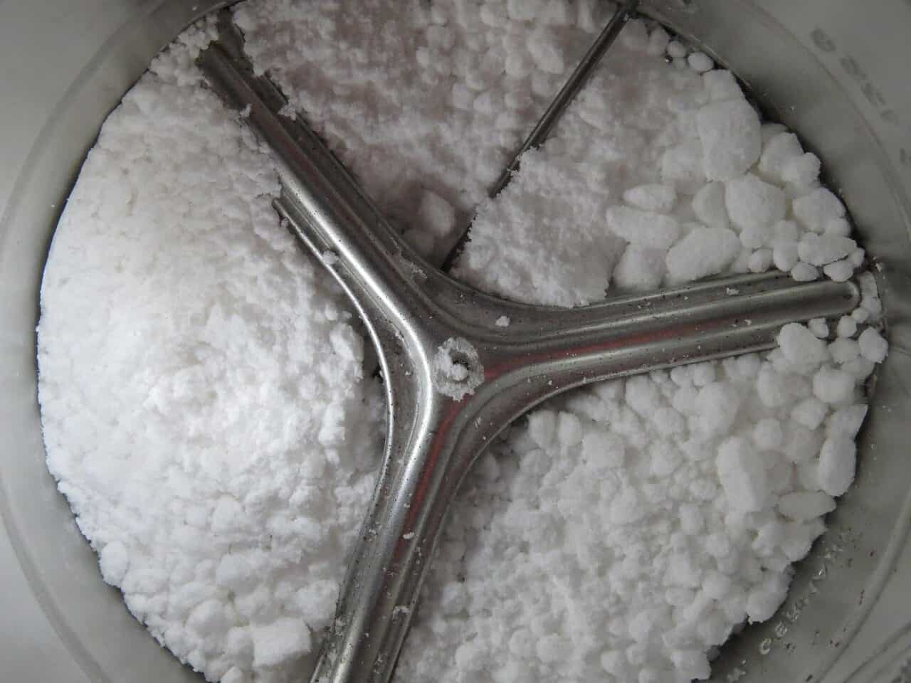
Las cribas vibratorias giratorias utilizan pesos excéntricos en un eje motor para crear un movimiento tridimensional. Esto combina el giro horizontal con la elevación vertical. Este movimiento complejo funciona muy bien para estratificar el lecho de material. Permite que las partículas más finas desciendan hasta la superficie del tamiz, mientras que las más gruesas permanecen en la parte superior. Ofrece una precisión excelente y es el estándar para el control de calidad y la separación de polvo fino.
Las cribas vibratorias lineales utilizan excitadores electromagnéticos o motores dobles contrarrotatorios. Crean un movimiento rectilíneo de alta frecuencia. Este movimiento desplaza eficazmente el material a través de una criba inclinada. Aunque ofrecen un rendimiento muy alto, el menor tiempo de permanencia en la criba puede reducir la eficacia de la separación en comparación con los sistemas giratorios. Sobresalen en el desbaste, la deshidratación y la clasificación de sólidos a granel.
Tamices centrífugos
Tamizadoras centrífugas trabajar en un principio diferente. El material se introduce en una cámara cilíndrica que contiene un eje central giratorio con paletas o sinfines. Estas paletas giran a gran velocidad, acelerando el material y lanzándolo hacia el exterior contra la criba cilíndrica.
La fuerza centrífuga generada impulsa la separación. Las partículas finas que se ajustan a la abertura de la malla pasan inmediatamente a través de ella. Las partículas más gruesas quedan retenidas y se desplazan a lo largo del cilindro hasta una salida de descarga independiente. Esta acción agresiva funciona muy bien para romper los grumos blandos y conseguir un alto rendimiento en un espacio compacto.
Cribas de tambor
Las cribas de tambor reproducen el suave movimiento del cribado manual. Utilizan un movimiento de volteo o balanceo lento y tridimensional para hacer caer el material en cascada a través de una plataforma de cribado casi horizontal. Esta acción suave minimiza el daño a las partículas. Esto la hace ideal para productos frágiles, delicados o esféricos.
El movimiento rotatorio proporciona un largo tiempo de retención. Esto da a cada partícula múltiples oportunidades de presentarse a una abertura. El resultado es una precisión de separación extremadamente alta, sobre todo en el caso de materiales difíciles de cribar por su forma o baja densidad. Para mantener la criba limpia durante el funcionamiento, suelen utilizarse plataformas de bolas o chorros de aire.
Tamices estáticos
Los tamices estáticos, incluidos los codos de tamiz y los tamices de alambre en cuña, son la forma más sencilla de equipo de separación. No tienen piezas móviles y dependen totalmente de la gravedad y de las características de flujo del material.
Normalmente, un lodo o una mezcla de líquido y sólido se introduce en la parte superior de una criba curva e inclinada. A medida que el material fluye por la superficie de la criba, el líquido y los sólidos finos pasan a través de las aberturas. Los sólidos más grandes quedan retenidos y se deslizan por el borde inferior. Su uso principal es la deshidratación, la separación líquido-sólido y la clasificación gruesa cuando la alta precisión no es el objetivo principal.
Cuadro 1: Análisis comparativo de los mecanismos de tamizado
|
Tipo de mecanismo
|
Principio operativo básico
|
Fuerzas primarias utilizadas
|
Características ideales de las partículas
|
Aplicaciones comunes
|
|
Vibratoria giratoria
|
El movimiento 3D (horizontal y vertical) fluidifica el material para obtener un alto rendimiento y precisión.
|
Gravedad, aceleración multiplanar
|
Polvos y gránulos secos y fluidos.
|
Ingredientes alimentarios, productos farmacéuticos, polvos químicos.
|
|
Vibratoria lineal
|
El movimiento lineal de alta frecuencia transporta el material a través de una criba inclinada.
|
Gravedad, aceleración lineal
|
Deshidratación, descascarillado de sólidos a granel.
|
Minería, áridos, reciclaje.
|
|
Centrífuga
|
Unas paletas giratorias de alta velocidad lanzan el material contra una criba cilíndrica.
|
Fuerza centrífuga, resistencia aerodinámica
|
Polvos propensos a la aglomeración; control de seguridad.
|
Molienda de harina, procesamiento de especias.
|
|
Criba de tambor
|
Movimiento de voltereta lento y en 3D.
|
Gravedad, volteo mecánico suave
|
Materiales esféricos, friables o ligeros.
|
Pellets de plástico, polvos metálicos, arena de sílice.
|
La ciencia de las mallas de tamiz
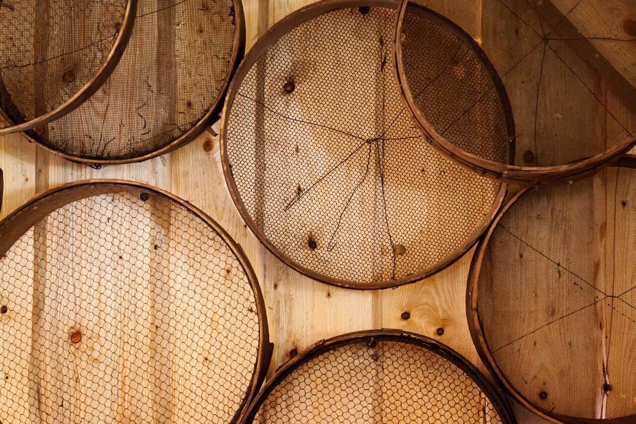
La malla del tamiz es el corazón de cualquier sistema de tamizado. Sin embargo, a menudo se pasan por alto sus especificaciones técnicas. La malla no es sólo un tamiz. Es un componente diseñado con precisión cuyo material, tejido y construcción controlan directamente la precisión de la separación, el rendimiento y la vida útil.
Especificaciones de la malla
Tres parámetros fundamentales definen una malla metálica: el número de mallas, el diámetro del alambre y el tamaño de la abertura.
El número de mallas se refiere al número de alambres por pulgada lineal (o 25,4 mm). Un mayor número de mallas suele significar un tamiz más fino.
El diámetro del alambre es el grosor de cada uno de los alambres utilizados para tejer la malla.
El tamaño de la abertura (o tamaño de la abertura) es el espacio real entre alambres paralelos adyacentes. Es la dimensión crítica que determina el tamaño de partícula que puede pasar. Estos tres parámetros están matemáticamente relacionados. Para un número de mallas determinado, un diámetro de alambre mayor dará lugar a una abertura menor y a una superficie abierta inferior.
Estas especificaciones están normalizadas para garantizar su coherencia y comparabilidad. Las normas más reconocidas son la ASTM E11 y la ISO 3310-1. Estas normas establecen tolerancias estrictas para las telas metálicas utilizadas en tamices de ensayo y tamizados industriales. La referencia a estas normas es crucial para las aplicaciones que requieren una distribución granulométrica certificada.
Tipos de tejido y su impacto
El patrón con el que se entrelazan los alambres afecta significativamente a las características de rendimiento de la malla.
El tejido liso es el tipo más común y básico. Cada hilo de urdimbre pasa alternativamente por encima y por debajo de cada hilo de trama. Crea una abertura cuadrada y estable y se utiliza para la mayoría de las aplicaciones de cribado de uso general.
En el tejido de sarga, cada alambre pasa por encima y por debajo de dos alambres adyacentes. Esto permite utilizar un diámetro de alambre más grueso para un número de mallas determinado. El resultado es una malla más resistente y duradera, adecuada para separaciones más finas y cargas más elevadas.
En el tejido holandés liso se utiliza un alambre de urdimbre más grande, más espaciado, y un alambre de trama más pequeño, entrelazados estrechamente. De este modo se crea una malla muy resistente que no tiene un recorrido rectilíneo. Esto hace que funcione más como un filtro. Destaca en la filtración a alta presión y la separación de sólidos de líquidos. La elección del tejido influye directamente en el porcentaje de superficie abierta. Esto, a su vez, influye en la capacidad de paso y la tendencia al cegamiento.
Ciencia material de las mallas
El material de la propia malla es una elección fundamental. Depende del entorno químico, térmico y abrasivo de la aplicación.
El acero inoxidable es el caballo de batalla de la industria. El tipo 304 es una opción de uso general. El tipo 316L ofrece una mayor resistencia a la corrosión gracias a su contenido en molibdeno. Esto hace que el 316L sea el estándar para aplicaciones farmacéuticas, alimentarias y químicas moderadamente corrosivas.
Los materiales sintéticos como el nailon y el poliéster ofrecen ventajas únicas. El nailon (poliamida) tiene una excelente resistencia a la abrasión y una gran elasticidad. Esta elasticidad permite a la malla estirarse y recuperarse. Esto puede crear un efecto de autolimpieza que reduce el cegamiento de la malla por partículas cercanas al tamaño.
El poliéster es conocido por su bajo alargamiento y su estabilidad dimensional. Esto significa que no se estira mucho bajo tensión. Esto, combinado con una buena resistencia química, lo convierte en la opción preferida para el tamizado húmedo y las aplicaciones en las que es primordial mantener una abertura precisa bajo carga.
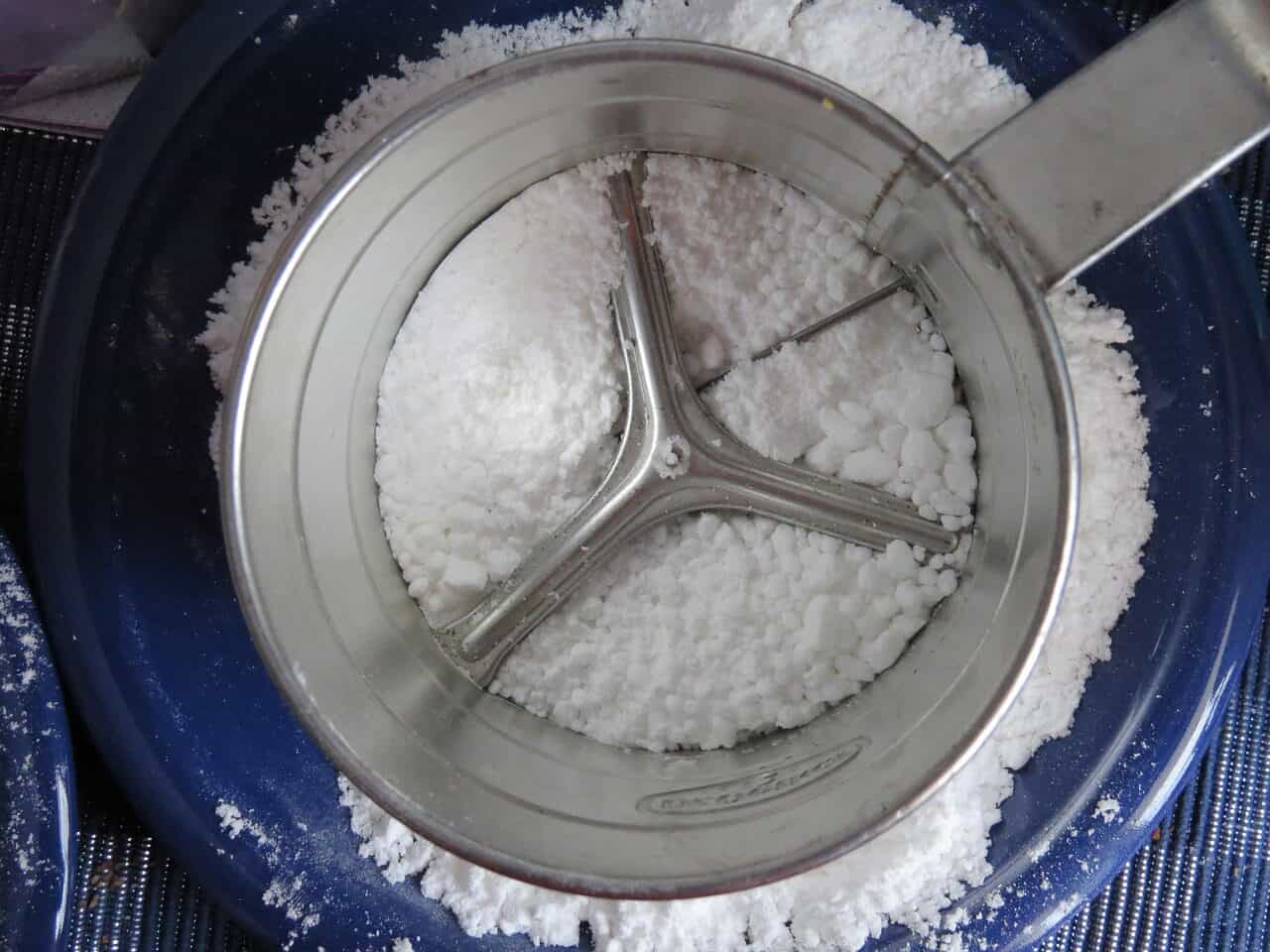
Tabla 2: Guía de selección del material de la malla del tamiz
|
Material
|
Propiedades clave
|
Lo mejor para
|
Evitar cuando
|
|
Acero inoxidable (316L)
|
Alta resistencia a la corrosión, tolerancia a altas temperaturas, higiénico.
|
Aplicaciones farmacéuticas, alimentarias y químicas corrosivas.
|
Materiales muy abrasivos (pueden desgastarse más rápidamente que las aleaciones especializadas).
|
|
Nylon (Poliamida)
|
Excelente resistencia a la abrasión, gran elasticidad (bueno para reducir el cegamiento).
|
Polvos abrasivos, materiales propensos a la acumulación estática.
|
Aplicaciones a altas temperaturas (>120°C), ácidos/bases fuertes.
|
|
Poliéster
|
Baja elongación, buena resistencia química, dimensionalmente estable.
|
Tamizado en húmedo, aplicaciones que requieren una estabilidad de apertura precisa.
|
Álcalis fuertes, entornos de alta abrasión.
|
|
Aleaciones especiales
|
Varía (por ejemplo, resistencia a altas temperaturas o a la corrosión extrema).
|
Entornos químicos o térmicos muy específicos y agresivos.
|
Aplicaciones de uso general (coste prohibitivo).
|
Optimización del rendimiento del tamizado
Poseer el equipo adecuado es sólo el primer paso. Alcanzar el máximo rendimiento requiere una comprensión técnica de las variables clave y un enfoque sistemático de la resolución de problemas. La optimización es un proceso continuo de medición, ajuste y resolución de problemas.
Indicadores clave de rendimiento
Para optimizar un proceso, primero hay que medirlo. En el tamizado, hay tres KPI fundamentales.
La eficacia del cribado es el parámetro más importante. Se calcula como el porcentaje de material de tamaño inferior en la alimentación que pasa correctamente al flujo de producto fino. Una eficiencia baja significa que se está perdiendo producto bueno en el flujo de material de gran tamaño.
El rendimiento es el volumen o la masa de material procesado por unidad de tiempo (por ejemplo, kilogramos por hora). Suele ser el principal motor comercial. Pero debe equilibrarse con la eficiencia.
La pureza del producto se refiere al nivel de contaminación en los flujos finales. Puede referirse al porcentaje de partículas de gran tamaño en el producto fino o al porcentaje de partículas finas en el producto de gran tamaño. El nivel aceptable viene dictado por la especificación del producto.
Parámetros técnicos para la optimización
En ingeniero puede manipular varias máquinas parámetros para influir en estos KPI.
La amplitud y la frecuencia de vibración son los controles principales de un tamiz vibratorio. Aumentar la amplitud o la fuerza del motor suele incrementar la velocidad de transporte y el rendimiento. Pero puede reducir el tiempo de retención y la eficacia. El ajuste del ángulo de avance de los contrapesos del motor modifica el patrón de flujo del material en la criba. Esto es crucial para optimizar la dispersión y la estratificación.
El ángulo de la criba, o inclinación, presenta un compromiso directo entre rendimiento y eficacia. Un ángulo más pronunciado aumenta la velocidad de transporte y el rendimiento, pero reduce el tiempo de retención del material en la criba. Esto reduce potencialmente la probabilidad de que una partícula la atraviese.
La velocidad de alimentación debe ser controlada y constante. La sobrecarga del tamiz, conocida como inundación del tamiz, crea un lecho de material demasiado profundo para una estratificación eficaz. Esto entierra las partículas finas, impidiendo que lleguen al tamiz y reduciendo drásticamente la eficacia. Un alimentador controlado es esencial para cualquier proceso de tamizado optimizado.
El tiempo de retención es la duración media que una partícula pasa en la superficie de la pantalla. Es función de los demás parámetros. Los tiempos de retención más largos aumentan la probabilidad de separación y mejoran la eficacia, pero a costa del rendimiento. El objetivo es encontrar el tiempo de retención mínimo que permita alcanzar la eficacia de separación requerida.
Problemas comunes de cribado
Sobre el terreno, vemos con frecuencia un puñado de problemas recurrentes que pueden resolverse con un planteamiento técnico. Comprender la causa de fondo es clave para aplicar una solución duradera.
Un problema habitual al que se enfrentan los ingenieros es el cegamiento de las mallas. En este caso, las partículas se alojan en las aberturas de la malla y las bloquean. Esto suele deberse a que las partículas cercanas al tamaño se atascan, o a que la humedad y la electricidad estática hacen que los polvos finos se adhieran a los alambres.
El bajo rendimiento es otra queja frecuente. Puede ser un síntoma de cegamiento de la criba. Pero también puede deberse a una energía vibratoria insuficiente, a un ángulo de cribado incorrecto que ralentiza el transporte o, simplemente, a una velocidad de alimentación excesiva.
La falta de precisión en la separación se traduce en un exceso de finos en el flujo de gran tamaño o de partículas gruesas en el producto fino. Esto suele indicar que la criba está desgastada o dañada. También puede deberse a la inundación de la criba, que impide una estratificación adecuada, o a una dinámica de vibración incorrecta que no consigue esparcir el material con eficacia.
La rotura prematura de la pantalla es un problema costoso. Suele deberse a la fatiga del metal como consecuencia de un tensado incorrecto de la malla. También puede verse acelerada por materiales muy abrasivos o por cargas de choque provocadas por el impacto incontrolado de grandes cantidades de material de alimentación contra la malla.
Tabla 3: Problemas comunes de tamizado: Causas técnicas y soluciones
|
Problema
|
Causa(s) técnica(s) común(es)
|
Solución(es) técnica(s)
|
|
Cegado/obstrucción del tamiz
|
Partículas de tamaño pequeño que se alojan en las aberturas de la malla; la humedad o la estática provocan la adhesión de partículas.
|
Instalar un sistema de descolmatado (bolas, deslizadores, ultrasonidos); ajustar la frecuencia de vibración; secar el material; utilizar malla antiestática.
|
|
Bajo Rendimiento
|
Vibración/movimiento insuficiente; ángulo de cribado incorrecto; cegado de la criba; velocidad de alimentación sobrecargada.
|
Aumentar la fuerza/frecuencia del motor; optimizar la inclinación de la criba; comprobar si hay cegamiento y solucionarlo; instalar un alimentador controlado.
|
|
Poca precisión de separación
|
Malla desgastada o dañada; velocidad de avance excesiva (lecho de material demasiado profundo); dinámica de vibración incorrecta.
|
Inspeccione y sustituya la criba; reduzca la velocidad de alimentación; ajuste los pesos del motor para optimizar la distribución y estratificación del material.
|
|
Rotura de pantalla
|
Fatiga del metal por tensado incorrecto; desgaste corrosivo o abrasivo del material; carga de choque por alimentación pesada.
|
Asegurarse de que se siguen los procedimientos correctos de tensado de la malla; seleccionar un material de malla más duradero (por ejemplo, nailon para la abrasión); controlar la alimentación para evitar impactos.
|
Tecnologías avanzadas y futuras
Aunque los principios básicos del tamizado se mantienen constantes, la tecnología sigue evolucionando. Está resolviendo retos de separación cada vez más difíciles, sobre todo en el ámbito de los polvos muy finos. Estos sistemas avanzados introducen nuevos principios físicos para superar las limitaciones de los equipos convencionales.
Sistemas de tamizado por ultrasonidos
El tamizado por ultrasonidos representa un importante avance en la separación de polvos finos. Esta tecnología aborda el principal reto del cribado de polvos de menos de 100 micras: el cegamiento de la malla causado por la estática y la tensión superficial.
El principio consiste en añadir una vibración de alta frecuencia y baja amplitud directamente sobre la malla del tamiz. Un transductor convierte la energía eléctrica en ondas ultrasónicas. Éstas se transfieren a la malla a través de un resonador. Esta vibración secundaria fluidifica la capa límite de partículas directamente sobre la superficie del tamiz.
Esta excitación ultrasónica rompe eficazmente los enlaces estáticos entre las partículas y entre éstas y los alambres de la malla. Prácticamente elimina el cegamiento y permite un cribado eficaz y de alto rendimiento de materiales que sería imposible separar sólo con la vibración convencional. Aunque son muy eficaces, estos sistemas añaden complejidad y coste. Requieren una cuidadosa integración y mantenimiento.
Tamizado por chorro de aire
El tamizado por chorro de aire no es una tecnología de producción, sino un instrumento de laboratorio fundamental para el análisis granulométrico. Es el método estándar para determinar la distribución granulométrica de polvos finos secos, especialmente para materiales de 20 µm a 2 mm.
Su principio es único. Se coloca una muestra en un único tamiz de ensayo dentro de una cámara sellada. Una boquilla giratoria, o varilla ranurada, situada debajo del tamiz sopla un chorro de aire hacia arriba. Este chorro de aire dispersa las partículas en el tamiz, rompe los grumos y despeja las aberturas de la malla.
Al mismo tiempo, se aspira un vacío desde debajo del tamiz. Este vacío arrastra las partículas finas dispersadas por el chorro de aire a través del tamiz. El proceso se cronometra y el material que queda en el tamiz se pesa para determinar la fracción de partículas de gran tamaño. De este modo se obtienen resultados altamente repetibles y precisos para el control de calidad y la I+D.
El auge del tamizado inteligente
El futuro del tamizado industrial pasa por la integración y la automatización. El auge de la Industria 4.0 está llevando los sistemas inteligentes a la vanguardia del control de procesos.
Esto incluye el desarrollo de sensores capaces de controlar el estado de las pantallas en tiempo real. Detectan desgarros o pérdidas de tensión antes de que se produzca una contaminación importante del producto. Los sistemas de tensión automatizados pueden garantizar que la malla esté siempre en su tensión óptima. Esto maximiza el rendimiento y la vida útil de la malla.
Además, la plena integración del PLC permite que la unidad de tamizado se convierta en una parte dinámica de la línea de proceso. Mediante el uso de bucles de retroalimentación de sensores aguas abajo (por ejemplo, analizadores de tamaño de partículas), el sistema puede ajustar automáticamente parámetros como la frecuencia de vibración o la velocidad del alimentador. De este modo, la calidad del producto se mantiene constante a pesar de las variaciones del material entrante.
Conclusión
El dominio de los equipos de tamizado no proviene de la familiaridad con la marca, sino de una sólida comprensión de sus principios fundamentales. Desde la física probabilística de la separación de partículas hasta la ciencia material de la propia malla, cada aspecto del sistema se rige por normas técnicas básicas verdades.
Al comprender cómo se aplican las fuerzas, cómo difieren los mecanismos y cómo se mide y optimiza el rendimiento, los ingenieros pueden transformar un simple separador en un instrumento de precisión. Este conocimiento es la clave para aumentar la eficiencia, garantizar la calidad del producto y resolver los problemas de separación más complejos.
- Técnicas avanzadas de corte de alimentos sólidos | Comprehensive Reviews in Food Science - Wiley https://ift.onlinelibrary.wiley.com/doi/abs/10.1111/1541-4337.12896
- Rebanado de alimentos en aplicaciones industriales | ScienceDirect https://www.sciencedirect.com/science/article/abs/pii/S0260877419303796
- Fundamentos de la ciencia y la tecnología de la confitería | Universidad de Wisconsin https://interpro.wisc.edu/courses/fundamentals-of-confectionery-science-and-technology-module-1-sugar-confections/
- Ingeniería alimentaria | Wikipedia https://en.wikipedia.org/wiki/Food_engineering
- Tecnología de elaboración de productos de confitería | IFT.org https://www.ift.org/news-and-publications/food-technology-magazine/issues/1999/december/columns/processing
- Visión general del corte por ultrasonidos | ScienceDirect Topics https://www.sciencedirect.com/topics/engineering/ultrasonic-cutting
- Fabricación avanzada de alimentos | USDA NIFA https://www.nifa.usda.gov/topics/advanced-food-manufacturing
- Controladores PLC para fabricación | Rockwell Automation https://www.rockwellautomation.com/en-us/products/hardware/allen-bradley/programmable-controllers.html
- Servomotores en la automatización de fábricas | Mitsubishi Electric https://mitsubishisolutions.com/what-does-a-servo-do-in-factory-automation/
- Comprender los servomotores para el diseño de automatización y control https://www.controldesign.com/podcasts/article/33015867/applications-of-the-servo-motors-power-and-precision