The Engineer’s Guide to Crystallographic Texture Formation: Mechanisms, Processes, and Properties
Introduction: Performance From Grains
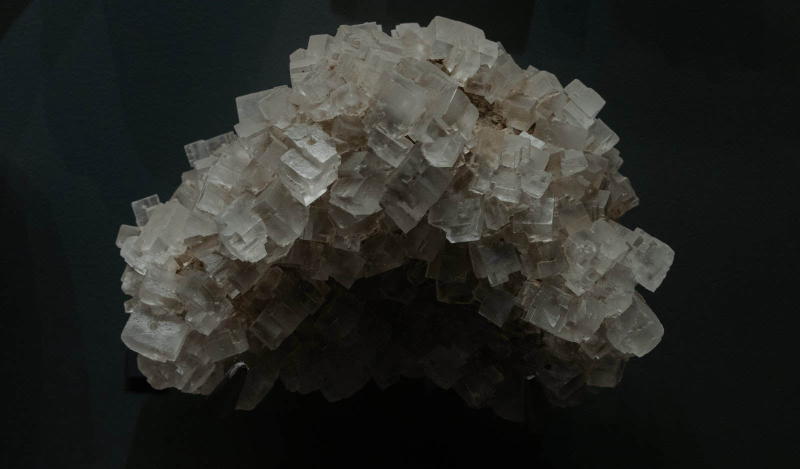
Picture a block of cast iron. Its crystals point in random directions. This gives it uniform properties, but it breaks easily. Now think about a steel sheet used for car panels. It can stretch into complex shapes without tearing.
The difference isn’t just what they’re made of. It’s the carefully designed internal structure. This structure is called crystallographic texture.
Crystallographic texture is when crystals in a material prefer certain orientations. The grains don’t point randomly in all directions. Instead, they line up in specific ways.
Texture formation is the process that creates this alignment. Physical forces during manufacturing drive it. These include plastic deformation, heat treatment, and cooling from liquid metal.
This guide breaks down how texture formation works. We’ll explore how engineers control it in key industrial processes. You’ll learn how it’s measured and understand its major impact on material properties. This knowledge separates ordinary materials from high-performance, engineered components.
Fundamentals of Representation
To control texture, we need a way to describe it. Understanding how to represent grain orientations is essential for analyzing and engineering material properties. This section gives you that critical language.
From Lattices to Grains
Every metal is built from atoms arranged in a repeating, three-dimensional pattern called a crystal lattice. We can describe how this lattice sits in space using a coordinate system attached to the crystal.
A polycrystalline material contains many individual crystals called grains. In a material with no texture, these countless grains point in completely random directions.
A textured material is different. Its grain orientations show a clear pattern. They cluster around one or more preferred directions. This non-randomness defines texture.
Visualizing Texture
We use specific graphical tools to see this non-randomness. The most common is the pole figure.
A pole figure is a two-dimensional map that shows how a specific crystal direction is distributed across all grains in the sample. For example, a {100} pole figure shows where the <100> directions of all crystals point relative to the sample’s dimensions, like its rolling and width directions.
Bright spots, or “poles,” on the figure show high concentrations of crystal planes aligned in a particular way. This directly indicates a preferred orientation.
An inverse pole figure works backward. It shows how a specific sample direction, like the rolling direction, relates to the crystal’s coordinate system. It answers: which crystal directions align with this sample direction?
The Complete Picture
Pole figures are powerful, but they only show a 2D projection of the orientation data. For a complete description, we need the Orientation Distribution Function (ODF).
The ODF gives the most complete, quantitative picture of texture. It’s a three-dimensional function that shows the probability of finding a grain with a specific orientation.
This function uses three Euler angles (φ1, Φ, φ2). These angles represent three rotations needed to rotate a reference crystal coordinate system to match any given grain’s coordinate system. A diagram would show the first rotation (φ1) about the Z-axis, the second (Φ) about the new X-axis, and the final (φ2) about the new Z-axis.
Specific, common textures often get names for convenience. In cubic metals, common texture components include Cube {001}<100>, Goss {110}<001>, and Brass {110}<112> orientations. The ODF lets us precisely measure the volume fraction and sharpness of these components.
Core Formation Mechanisms
Texture doesn’t happen by accident. It results directly from physical processes that force crystals to rotate and rearrange. Understanding these core mechanisms is essential for predicting and controlling a component’s final texture.
Plastic Deformation Texture
When a metal is plastically deformed, its grains change shape. This shape change happens mainly through crystalline slip.
Crystalline slip is when atomic planes slide over each other along specific crystal directions. This process is inherently directional. It occurs most easily on specific slip systems—a combination of a slip plane and a slip direction.
As the material deforms, each grain tries to accommodate the imposed shape change. This forces the crystal lattices to rotate. Grains rotate from “hard” orientations, where slip is difficult, toward “soft” or stable orientations, where slip can more easily handle the strain.
Over large strains, like those in rolling or drawing, these individual rotations add up. This results in a strong and well-defined deformation texture.
We use theoretical frameworks to predict these textures. The Taylor model is a foundational concept that assumes strain is uniform across all grains. It effectively predicts final deformation textures in many metals by calculating required slip system activity and resulting lattice rotation. The Sachs model assumes uniform stress, providing a different prediction of expected behavior.
Besides slip, mechanical twinning is another important deformation mechanism. Twinning involves part of the crystal lattice suddenly shearing into a new orientation that mirrors the parent lattice.
This mechanism is particularly important in metals with few available slip systems. Examples include hexagonal close-packed (HCP) metals like magnesium, titanium, and zirconium. It also plays a role in body-centered cubic (BCC) metals at low temperatures or high strain rates. Twinning causes large, sudden reorientations and can dramatically change texture development.
Annealing Texture
Deformation textures often aren’t the final desired state. They typically have high stored energy and poor ductility. Annealing, a heat treatment process, recovers these properties and creates new textures in the process.
When a deformed material is heated, new, strain-free grains form and grow, consuming the old, deformed structure. This process is called recrystallization. It results in a distinct recrystallization texture.
Two main theories explain this texture formation, and they often compete: oriented nucleation and oriented growth.
Oriented nucleation theory says that nuclei with specific orientations form preferentially. These nuclei may start in highly strained regions of the deformed microstructure, such as at grain boundaries or within deformation bands, that already have the orientation of the final recrystallization texture.
Oriented growth theory argues differently. It says nuclei of many orientations may form, but only those with a specific orientation relationship to the surrounding deformed matrix grow fastest. This advantage comes from their grain boundaries’ high mobility, allowing them to rapidly consume the stored energy of the deformed structure.
In reality, both mechanisms likely contribute to the final recrystallization texture. Their relative importance depends on the material, the degree of prior deformation, and the annealing conditions.
After recrystallization, if temperature remains high, grains continue to grow to reduce total grain boundary area and its associated energy. This is grain growth.
During this process, texture can continue to evolve. This happens because grain boundary mobility and energy depend on the misorientation between adjacent grains. Grains with orientations that create low-energy or high-mobility boundaries with their neighbors will grow at others’ expense, leading to a grain growth texture.
Solidification and Transformation
Texture can also form as a material solidifies from liquid or transforms from one solid phase to another.
During solidification, especially in casting processes where heat is removed directionally, crystals tend to grow fastest along specific crystal directions. In cubic metals, this is often the <100> direction.
This preferential growth creates columnar grains—elongated crystals aligned with the heat flow direction. The result is a strong solidification texture, which can significantly influence the cast component’s properties.
Solid-state phase transformations also provide a powerful route for texture formation. When a material transforms—for example, from high-temperature austenite (FCC) phase to low-temperature ferrite (BCC) phase in steel—the new phase inherits a crystallographic relationship from the parent phase.
Theoretically, many different orientation variants of the new phase can form from a single parent grain. However, due to local stresses, strain accommodation, and interfacial energy effects, only a specific subset of these variants may actually form. This is called variant selection.
This selective process means that if the parent phase has strong texture, the product phase can develop even stronger and more complex texture. Controlling variant selection during phase transformations is a key strategy for texture engineering in advanced steels, titanium alloys, and other transforming systems.

Texture in Industrial Practice
The theoretical mechanisms of texture formation apply directly to real-world manufacturing. By controlling process parameters, engineers can generate specific textures to achieve desired material performance. This is clearly seen in common metal forming operations.
Rolling Textures
Rolling is a dominant process for producing sheet metal. During rolling, the material undergoes plane-strain compression—severe plastic deformation that leads to strong and characteristic textures.
In face-centered cubic (FCC) metals like aluminum and copper, the rolling texture type depends on the material’s stacking fault energy (SFE). Low-SFE materials like brass develop “Brass-type” texture, which includes the Brass {110}<112> component. High-SFE materials like aluminum and copper develop “Copper-type” texture, characterized by components like the S {123}<634>.
In body-centered cubic (BCC) metals like ferritic steel, rolling textures are typically described by fibers. The α-fiber consists of orientations with a <110> direction parallel to the rolling direction. The γ-fiber consists of orientations with a <111> direction parallel to the sheet normal.
When these rolled sheets are subsequently annealed, the deformation textures transform. For example, in many FCC metals, the Cube {001}<100> texture component becomes dominant after recrystallization. This is crucial for certain applications. In steels, controlling the γ-fiber intensity is critical for formability.
Extrusion and Drawing
Processes like extrusion and wire drawing involve pushing or pulling material through a die. This results in axisymmetric material flow. This deformation mode produces strong fiber textures.
In a fiber texture, a specific crystal direction in most grains aligns with the principal deformation axis—the extrusion or drawing axis. However, the grains can have any rotational position around this axis.
For FCC metals, a dual <111> and <100> fiber texture is common. The relative strength of these two components depends on the material’s temperature and SFE. For BCC metals, a strong <110> fiber texture typically results from drawing. These textures directly create the high strength of drawn wires.
Table 1: Textures in FCC Metals
Processar | Deformation Mechanism | Typical Deformation Texture Components | Typical Recrystallization Texture Components |
Hot/Cold Rolling | Crystalline Slip (Plane Strain) | Copper-type (S, Copper) or Brass-type (Brass, Goss) | Cube {001}<100>, Goss {110}<001> |
Extrusion/Drawing | Crystalline Slip (Axisymmetric) | Dual <111> and <100> fiber | Often sharpens the <100> or <111> fiber |
Thin Film Deposition (PVD) | Surface Diffusion, Nucleation | <111> or <100> fiber perpendicular to substrate | N/A (Texture forms during growth) |
Modern Characterization Techniques
To control texture, we must measure it accurately. Modern materials science offers a suite of powerful techniques. Each provides a unique window into a material’s crystallographic architecture, from bulk average to micro-scale detail.
Bulk Texture Measurement
For macroscopic, average measurement of texture over a large material volume, we use diffraction-based methods. These techniques rely on Bragg’s Law to determine crystal plane orientation.
X-ray diffraction (XRD) is the most common laboratory technique for texture analysis. An X-ray beam hits the sample, and detectors measure diffracted beam intensity at various angles. By tilting and rotating the sample, a series of pole figures can be constructed.
XRD’s primary limitation is its shallow penetration depth, typically micrometers in most metals. This makes it inherently surface-sensitive. While excellent for sheets and coatings, it may not represent a thick component’s true bulk texture.
To probe true bulk texture, we use neutron diffraction. Neutrons have much higher penetration depths than X-rays. They can pass through several centimeters of most engineering materials. This allows true, volume-averaged measurement. The drawback is that neutron diffraction requires a large-scale facility, such as a nuclear reactor or spallation source, limiting its accessibility.
Micro-Texture Measurement
For spatially resolved texture understanding, Electron Backscatter Diffraction (EBSD) is the dominant technique. Integrated into a scanning electron microscope (SEM), EBSD provides orientation data at the sub-micron level.
In EBSD, a stationary electron beam interacts with a highly tilted sample. Electrons backscattered from the crystal lattice form a characteristic Kikuchi pattern on a fluorescent screen. This pattern directly fingerprints the crystal orientation at that point.
By scanning the beam across the sample surface, EBSD can generate detailed orientation maps. These maps simultaneously reveal crystallographic texture, grain size and shape, grain boundary character, and local plastic strain variations. This provides an unparalleled link between microstructure and texture.
From practical experience, sample preparation is the most critical step for successful EBSD. When preparing a sample for EBSD analysis, achieving a damage-free, flat surface is essential. We find that a final polishing step using colloidal silica suspension is often critical for obtaining high-quality Kikuchi patterns, especially in softer materials like copper.
Table 2: Comparison of Characterization Techniques
Technique | Principle | Information Provided | Sample Volume | Pros | Cons |
X-ray Diffraction (XRD) | Bragg Diffraction of X-rays | Pole figures, ODF (average) | Surface (μm depth) | Accessible, fast, standardized | Surface-sensitive, limited spatial resolution |
Electron Backscatter Diffraction (EBSD) | Diffraction of Backscattered Electrons | Orientation maps, grain boundaries, micro-texture | Surface (nm depth, μm to mm area) | High spatial resolution, links texture to microstructure | Slow for large areas, requires extensive sample prep |
Neutron Diffraction | Bragg Diffraction of Neutrons | Pole figures, ODF (true bulk average) | Bulk (cm³ volume) | True bulk measurement, good for coarse grains | Requires large-scale facility, low spatial resolution |
The Engineering Consequence
The ultimate reason we study and control texture formation is its profound and direct impact on material properties. Texture is the primary source of anisotropy in polycrystalline materials. Engineering this anisotropy is key to optimizing component performance.
Anisotropy of Mechanical Properties
Anisotropy is how a property varies with direction. In a textured material, mechanical properties like strength and ductility are no longer uniform.
A rolled sheet’s yield strength can be significantly higher in one direction compared to another. This happens because applied stress resolves differently onto available slip systems depending on loading direction relative to preferred crystal orientations.
Perhaps the most critical impact is on formability, particularly in sheet metal forming. A sheet’s ability to be drawn into a deep cup shape without tearing is quantified by the Lankford coefficient, or r-value. This parameter directly measures the sheet’s resistance to thinning.
A high average r-value is highly desirable for deep-drawing applications. This property is achieved by intentionally creating strong γ-fiber (<111> || Normal Direction) texture during the steel’s rolling and annealing cycles. For instance, deep-drawing quality steels are engineered to have high average r-value (>1.5). This directly results from controlling texture formation during rolling and annealing.
Anisotropy of Functional Properties
Texture’s influence extends beyond mechanical behavior to physical and functional properties. In many advanced applications, this is the primary reason for texture control.
In electrical engineering, electrical steels’ magnetic properties are paramount. Iron’s “easy” magnetization direction is the <001> crystal direction. To minimize energy loss in transformer cores, manufacturers produce steel sheets with sharp Goss texture ({110}<001>).
This texture aligns the easy <001> magnetization direction along the sheet’s rolling direction. This corresponds to the magnetic flux direction in the transformer, dramatically improving its efficiency.
In the nuclear industry, zirconium alloys are used as fuel cladding. These HCP materials exhibit anisotropic thermal expansion and irradiation-induced growth. Controlling texture during tube manufacturing is absolutely critical to ensure dimensional stability and prevent failure during reactor operation.
Table 3: Texture-Property Relationships
Material | Key Texture Component(s) | Controlled Property | Engineering Application |
Electrical Steel | Goss Texture ({110}<001>) | Low Magnetic Core Loss | Transformer Cores |
Aluminum Can Sheet | Balanced Cube & Rolling Textures | High Formability, Earing Control | Beverage Cans |
Aerospace Ti-6Al-4V | Basal/Transverse Texture | High Strength, Fatigue Resistance | Fan Blades, Airframe Structures |
Copper Interconnects | <111> Fiber Texture | High Electromigration Resistance | Microelectronic Devices |

Conclusion: Mastering Materials
We have journeyed from crystallographic texture’s fundamental definition to the complex physics governing its creation. We have seen how texture formation is not random but a direct consequence of deformation, recrystallization, and phase transformation.
By understanding these core mechanisms, we can see how industrial processes like rolling and drawing sculpt materials’ internal architecture. We have also explored modern techniques used to measure this architecture. Most importantly, we understood its critical impact on material anisotropy.
The central message is clear: texture is a powerful, controllable microstructural feature. The ability to understand and engineer texture formation is a cornerstone of modern materials design. It enables creating optimized materials that push performance boundaries in applications from aerospace and energy to electronics.
Looking forward, texture formation principles are becoming even more critical with advanced manufacturing methods like additive manufacturing. These create unique thermal cycles and solidification conditions that present new textural challenges and opportunities. Mastering texture is, and will continue to be, essential for mastering materials.
- Materials Science and Crystallography – ASM International https://www.asminternational.org/
- Crystallography and Materials Science – NIST https://www.nist.gov/
- Crystallographic Texture – Wikipedia https://en.wikipedia.org/wiki/Texture_(crystalline)
- Materials Characterization Standards – ASTM International https://www.astm.org/
- Metallurgy and Materials Engineering – ASME https://www.asme.org/
- Materials Science Research – ScienceDirect https://www.sciencedirect.com/topics/materials-science/crystallographic-texture
- Materials Processing and Manufacturing – SME https://www.sme.org/
- Electron Backscatter Diffraction (EBSD) – Oxford Instruments https://www.oxinst.com/
- Materials Testing and Analysis – ISO https://www.iso.org/
- Materials Engineering Education – MIT OpenCourseWare https://ocw.mit.edu/